


Testing the Ignition Coil – for Absolute Beginners
Testing the ignition coil, or rather the Ohmic resistance of the primary & secondary windings of an ignition coil using a multimeter is a classic procedure.
Unfortunately, this test can only provide limited insight into the condition of the ignition coil because the condition of the ignition coil is not measured under load/in operation.
Thus, while an ignition coil that is no longer in perfect condition might still provide correct resistance values (within the scope of measurement accuracy), it may no longer be functional.
However, resistance measurement of the primary winding should ensure that the ignition coil does not destroy a new electronic ignition system.
A test of the windings might furthermore contribute to troubleshooting the ignition in case other problems exist.
A classic ignition coil includes two separate coils of wound wire:
- the primary winding
- and the secondary winding
- Primary = primary winding, in Ohms (Ω)
- Secondary = secondary winding, in kiloOhms (kΩ)
All Ohmic values for the primary winding – which is our primary focus – are in the (desired) range of approx. 3Ω.
Preparations:
During operation, up to 40,000V can be applied to an ignition coil.
Therefore, never measure the resistance of an ignition coil during operation.
- Disconnect the ignition coil completely from the wiring!
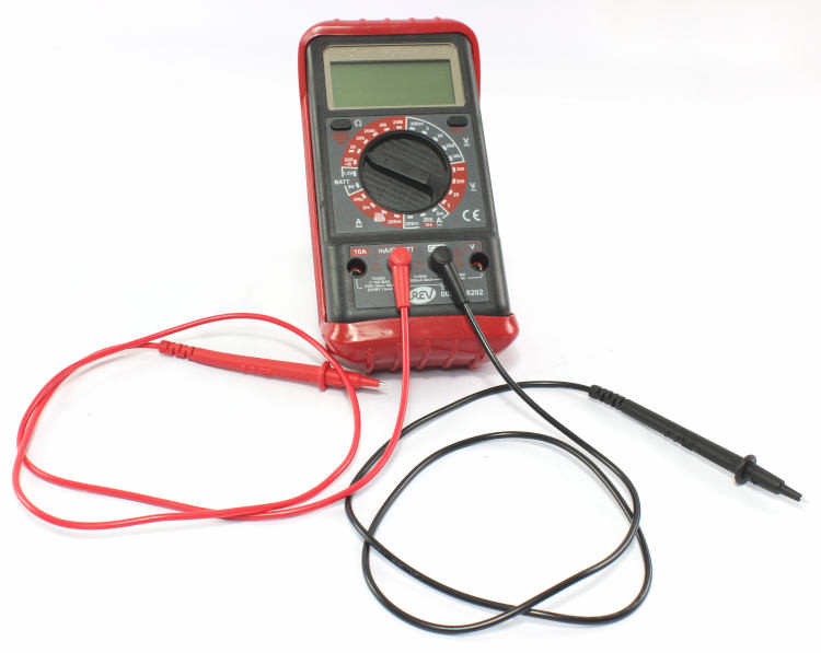
If the ignition coil is not completely disconnected from the wiring, erroneous values might be measured. Thus, remove all cables from the ignition coil before measuring. - The measuring instrument (usually) has several sockets:
- 10A
- V Ω mA (Ω is the symbol for Ohm that we need here)
- COM (COM is short for common, i.e. common ground)
- Set the multimeter to Ω.
- Plug the measuring cables into the multimeter:
- black cable into the COM / ground socket
- red cable into the Ω socket
Measuring the resistance of the multimeter cables
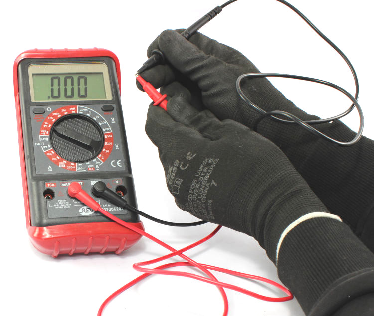
The instrument will display a resistance value of the cables. Depending on the quality and measuring accuracy of the multimeter, this value might be zero.
Note this value. For the subsequent primary circuit measurement, it has to be subtracted from the measured value.
Measuring the resistance of the ignition coil primary winding:
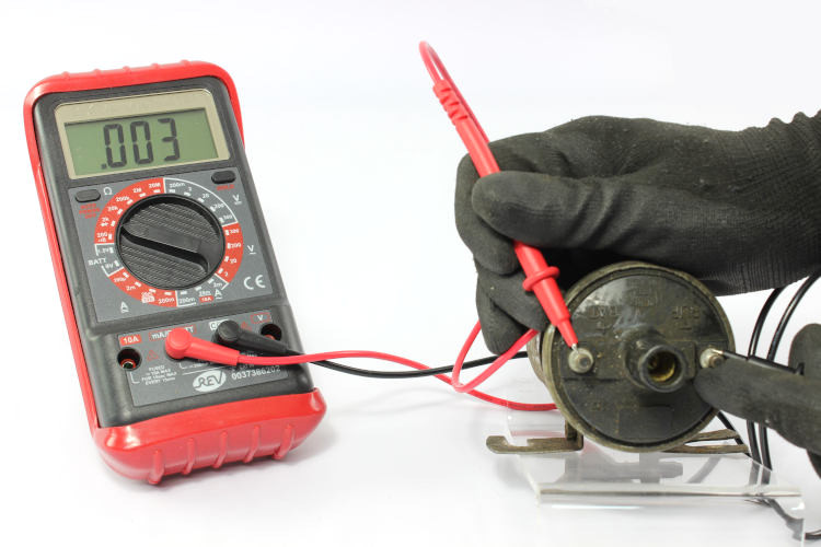
- Select the smallest possible Ohmic measuring range. Often, it is indicated as “200” on the instrument.
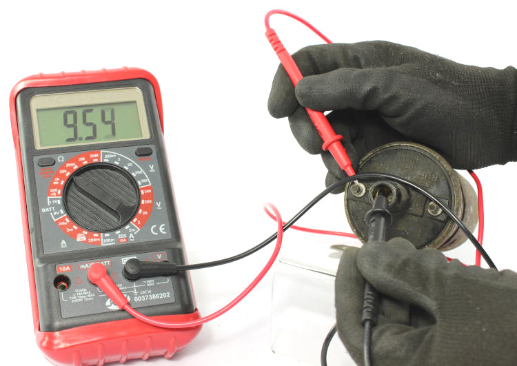
Explanation: “200” is the smallest measuring range, provided for all resistors up to 200Ω (this is perfect for the primary resistance of the coil). - Connect the red probe tip to the positive terminal & the black probe tip to the negative terminal of the ignition coil.
These are labelled “+” and “–” or “1” and “15”. - The instrument displays the resistance of the primary winding (including the cables). If the cable resistance value was > 0, subtract that value from the displayed value.
Measuring the resistance of the secondary winding (1)
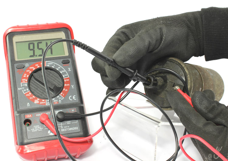
- Set the multimeter to the kiloOhm measuring range. It is often indicated as “20k” (for resistors up to 20kΩ) on the instrument.
- Connect the red probe tip to the negative terminal & the black probe tip to the high-voltage contact of the ignition coil.
This is the point where the cable going to the distributor (terminal tower of the coil) will be plugged in. - The resistance of the secondary winding is displayed.
Measuring the resistance of the secondary winding (2)
- Connect the red probe tip to the positive terminal & the black probe tip to the high-voltage contact of the ignition coil.
- The resistance of the secondary winding is displayed.
The measured value must be identical to the value of the previous measurement.
Information on the measured values
A resistance value that is too high indicates a broken wire.